MCP4131 digital potentiometer


JEDER KANN DAS!!!

von Edi · 13/11/2023
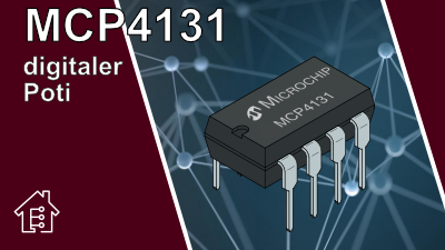
The MCP4131 digital potentiometer is controlled via the SPI interfaces. There are single (MCP41x1) and dual (MCP42x1) potentiometer versions, but we will focus on the single potentiometer here.
There is the potentiometer with 7-bit resolution, which corresponds to 128 resistors and 129 steps and an 8-bit resolution, with 256 resistors and 257 steps.
The CS pin (chip select) pin or also called SS (slave select) in the SPI interface is active when it is pulled LOW. The serial clock pin is labeled SCK and the SDI/SDO pin is used to receive the data. The IC is supplied with voltage at VSS (GND) and VDD. GND is connected to pin P0B and the voltage to pin P0A. The set voltage, which we have set via SPI, can now be taken from the P0W pin.
					#include <SPI.h>

const byte CSPin = 4;
const byte analogInPin = 17;  //A0
const byte maxPotiSteps = 128;  // 0 - 128 or 0 - 255 Steps
byte address = 0x00;

void setup() {
  Serial.begin(115200);
  pinMode (CSPin, OUTPUT);
  pinMode (analogInPin, INPUT);
  SPI.begin();
}

void loop() {
  setPotValue(5);
  readPotValue();
  delay(1000);
  setPotValue(80);
  readPotValue();
  delay(1000);
  setPotValue(maxPotiSteps);
  readPotValue();
  delay(1000);
  setPotValue(50);
  readPotValue();
  delay(1000);
}

void setPotValue(int value) {
  digitalWrite(CSPin, LOW);
  delay(20);
  SPI.transfer(address);
  SPI.transfer(value);
  delay(100);
  digitalWrite(CSPin, HIGH);
}

void readPotValue() {
  int sensorValue = analogRead(analogInPin);
  Serial.println(sensorValue);
  delay(100);
}
★☆★ If you want to support the channel via ★☆★
or via
Tags: MCP4131

Edi's Techlab


| Cookie | Dauer | Beschreibung |
|---|---|---|
| cookielawinfo-checkbox-analytics | 11 months | This cookie is set by GDPR Cookie Consent plugin. The cookie is used to store the user consent for the cookies in the category "Analytics". |
| cookielawinfo-checkbox-functional | 11 months | The cookie is set by GDPR cookie consent to record the user consent for the cookies in the category "Functional". |
| cookielawinfo-checkbox-necessary | 11 months | This cookie is set by GDPR Cookie Consent plugin. The cookies is used to store the user consent for the cookies in the category "Necessary". |
| cookielawinfo-checkbox-others | 11 months | This cookie is set by GDPR Cookie Consent plugin. The cookie is used to store the user consent for the cookies in the category "Other. |
| cookielawinfo-checkbox-performance | 11 months | This cookie is set by GDPR Cookie Consent plugin. The cookie is used to store the user consent for the cookies in the category "Performance". |
| viewed_cookie_policy | 11 months | The cookie is set by the GDPR Cookie Consent plugin and is used to store whether or not user has consented to the use of cookies. It does not store any personal data. |